Flow control valves
To limit or regulate flows up to 380 l/min [100 US gal/min] at pressures up to 450 bar [6,500 psi], we provide flow-control valves in restrictive, priority, and divider/combiner cartridge types. For additional features such as fully adjustable flow or free-reverse flow, combination valves in manifolds are also available.
Features and benefits
- Variety of solutions are available, from needle valves to pressure compensated flow dividing/combining.
- Pressure compensated flow controls maintain constant flow independent of load pressure.
- Restrictive-type can be used in meter-in or meter-out applications.
- Priority-type are well suited for steering applications.
- Flow divider/combiners help provide synchronized flow for cylinders or wheel motors.
- Velocity fuse valves provide protection in the event of a hose break.
- Adjustable or non-adjustable pressure compensated flow regulators are available.
- Fixed or adjustable priority bypass type flow regulators are available.
- Adjustable flow controls are available with or without free reverse flow check.
Applications
- Agriculture
- Construction
- Cranes and material handling
- Forestry
- Lawn and turf
- Road building
Basic operation
Flow control valves may be either non-compensated or compensated. Non-compensated valves feature an adjustable orifice, where the flow across the valve depends on the pressure differential and the size of the orifice. These valves can also include an integrated reverse flow check valve. Pressure compensated valves include an orifice that works in conjunction with a compensator. These can be two ported (restrictive type) or three ported (priority type), which gives the option of a priority, controlled flow with excess flow available to be used for secondary functions. Spool type flow divider / combiner valves are also available, which feature two spools linked mechanically, providing equal flow and individual compensation. Velocity fuses are valves that close when a pre-determined pressure drop across an orifice is reached.
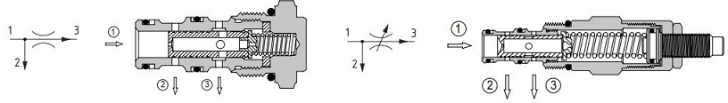
Needle valves
Needle valves provide a means to vary a restriction and provide a pressure drop or control a flow from port 1 to 2 or port 2 to 1. The flow is a function of the effective orifice between the two ports.
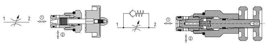
Pressure-compensated, restrictive-type valves
Valves of this type allow a flow from port 1 through an orifice in the center of the spool, causing a pressure differential. This differential causes the spool to move back against a spring and restrict flow out of the valve at port 2. If the pressure differential changes, the spool will compensate and further restrict or open the flow out at port 2.
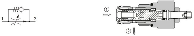
Pressure-compensated, restrictive-type valves with reverse free flow
These valves are pressure compensated and fully adjustable, which allow the operator to completely close the line between ports 1 and 2. A reverse free flow check is also built into the design from port 2 to 1. The adjustable orifice is independent of the compensating spool, which senses the pressure difference across the orifice and moves to control the outlet flow by restriction the exit holes to port 2.
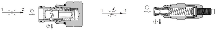
Pressure-compensated, priority-type valves
These valves are pressure compensated, three ported, priority type flow regulators. Once the flow setting is reached from port 1 to port 3, excess flow is diverted to port 2 and can be used in a separate part of the circuit.
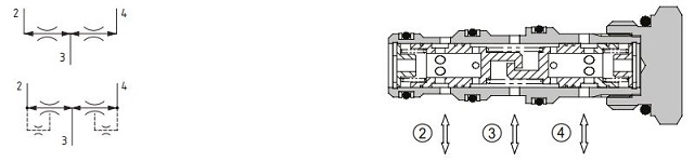
Flow dividers/combiners pressure-compensated valves
These valves are pressure-compensated spool-type flow divider/combiners. They split an inlet flow into two, maintaining the division independent of changes in pressure. They can also combine two flows accommodating changes in pressure.
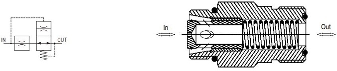
Velocity fuses
These valves are normally open and designed to close when the flow setting is reached. Depending on the design, the valve will close completely or to a pre- determined low flow. When installed into or next to an actuator, they can protect against catastrophic hose failure. An accelerating load will be slowed if the speed corresponds to a flow greater than the set flow. The valve will only open when the load pressure drops to less than the spring pressure (typically approximately 5.5 bar [80psi]).
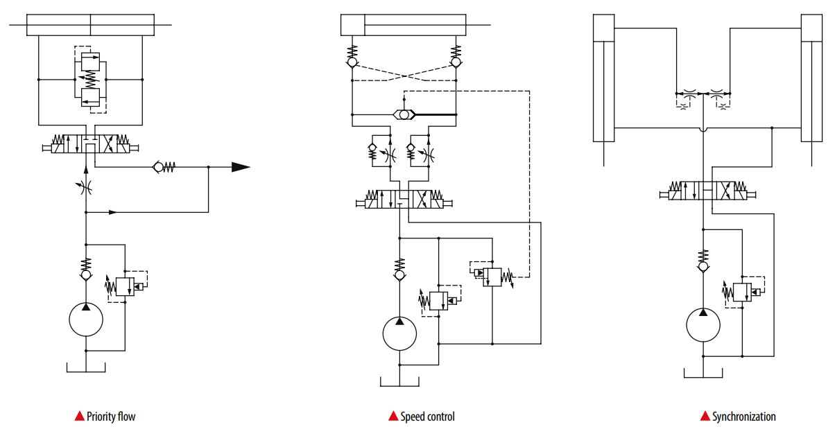
Typical application diagrams